Toroidal transformers
With toroidal cores used by InduComp, you benefit from low specific iron and eddy current losses. The low no-load losses allow the production of energy-efficient devices. The dimensions of the toroidal cores can be flexibly adapted to the needs of the company, ensuring a customized product. We have extensive experience in designing and manufacturing toroidal transformers, which always meet the expected quality requirements.
Advantages of Toroidal Transformers
Toroidal transformers are special transformers in which high-permeability electrical steel is wound into a ring-shaped core. During the manufacturing process, the magnetic material undergoes cold deformation, which deteriorates the magnetic properties of the base material. Therefore, the desired permeability and all other parameters, such as specific core losses, must be restored through final heat treatment (usually in an inert gas atmosphere) called final annealing.
The resulting cores are almost gap-free, making the no-load currents of toroidal transformers generally much lower compared to values of laminated E-core transformers.
Industrial Usability
Toroidal transformers are used in many industries due to their efficiency, which provides several advantages over other types of transformers. They are especially popular in applications where space and weight are limited, and where low electromagnetic interference (EMI) emission is important or needs to be minimized. Their use is common in electronic and electrical devices, lighting technology, robotics, audio equipment, and medical equipment.
Manufacturing of Toroidal Transformers at InduComp
For the transformers manufactured at InduComp, we mainly use grain-oriented FeSi3% quality material with high saturation magnetic flux density. (For example, M111-30P according to EN 10107 or 30P110 according to JIS C2553 standards.)
What Characterizes InduComp Toroidal Transformers?
InduComp’s toroidal cores have low specific core and eddy current losses. The low no-load losses allow customers to manufacture energy-efficient devices. The dimensions of the toroidal cores can be flexibly adapted to customer requirements. Depending on the transmitted power, a certain volume is needed, but the available space in the customer’s device can be utilized. The transformer can be mounted by filling the interior with polyurethane resin, allowing the transformer to be fixed with a screw through the central hole. Special toroidal winding machines distribute the turns evenly over the entire perimeter of the core. This winding technology provides very low magnetic leakage, so adjacent electrical circuits are less affected by magnetic noise. Due to this construction, toroidal transformers also have good magnetic coupling between the primary and secondary windings, and the low leakage inductance can be ignored when calculating load voltages. However, in the event of a short circuit, relatively large short-circuit currents can be observed, making protection with fuses generally unavoidable. Additionally, self-resetting thermal cut-offs (normally closed NC switches) or thermal fuses can be integrated as thermal protection.
Due to the described construction, high inrush currents can also occur when starting the transformer. Particularly high-power transformers with low winding resistance can create large inrush current peaks in the first periods until they stabilize.
Requirements for Toroidal Transformers
IEC 61558-1
The requirements for transformers (including toroidal transformers) are described in the 61558-1 standard: Safety of transformers, reactors, power supply units, and similar products. Part 1: General requirements and tests (IEC 61558-1:2017).
UL label
Optional UL marking according to UL 5085-1 (formerly UL 506) under file number E242328.
ENEC label
Optional ENEC marking according to EN IEC 61558-1:2019 and EN 61558-2-4:2009 or EN 61558-2-4:2021 (insulation transformers) or EN IEC 61558-1:2019 and EN 61558-2-6:2009 or EN 61558-2-6:2021 (safety insulation transformers).
IEC 60601
Optionally designed for use in medical devices according to the IEC EN 60601 / UL2601 standard. Specifically for medical equipment, designed according to IEC 60601-1:2005+ Cor.:2006+ Cor.:2007+ A1:2012; German version EN 60601-1:2006+ Cor.:2010+ A1:2013 Medical electrical equipment. Part 1: General requirements for basic safety and essential performance.
The transformer can be designed according to point 15.5 for network power transformers for medical electrical equipment and sub-point 8.5 for isolating transformers.
IEC 62368
Optionally, the EN 62368 standard Annex G can be considered: Audio/video, information, and communication technology equipment – Part 1: Safety requirements (IEC 62368-1:2018); German version EN IEC 62368-1:2020 + A11:2020.
The most important safety aspect of transformers is the galvanic isolation and insulation of the primary and secondary circuits. This provides safety and protection against electric shock. If the insulation is double insulation (see also reference IEV 195-06-08 in the Electropedia: The World’s Online Electrotechnical Vocabulary from the International Electrotechnical Commission), this helps classify electrical devices according to insulation class II.
Additional Options and Designs
– Open design
– Residual hole potting
– Potted in polyamide housing
– Flexible wire connections with or without Faston receptacles
– With multi-pole connectors (e.g., Molex, AMP, Tyco, Stocko, Druseidt, ContaClip, etc.)
– With ring cable lugs according to DIN 46234 or tubular cable lugs according to DIN 46235 for durable connection of high secondary currents
– Magnetic shielding (Mumetal or magnetic shielding on the outer circumference with electrical tape)
– Statical shield between primary and secondary to reduce capacitive interference/over coupling
– Custom specific constructions
Why Purchase Toroidal Transformers from InduComp?
Reliability and Experience
InduComp has extensive experience in designing and manufacturing toroidal transformers. Customer feedback also confirms that we flexibly meet the needs of companies and deliver ordered products on time.
Catering to Individual Needs
We design and manufacture toroidal transformers according to the customer’s request. This way, you receive a product that contributes to improving energy efficiency.
Safety
We subject each of our products to a 100% quality inspection, thereby guaranteeing optimal performance.
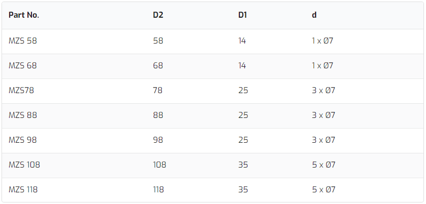
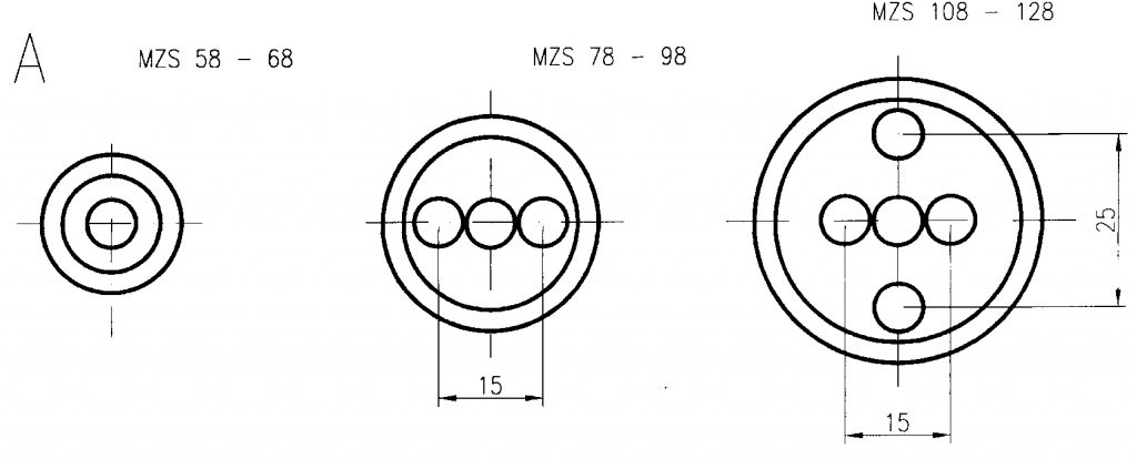
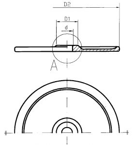
Available sizes of mounting plates